8 minutes
Raytracer 6: Rectangles, Cornell Box
Last time, we finished our GPU port. That is very valuable because GPUs are so fast, we can iterate faster when prototyping new techniques. And we implemented emissive materials. We can make spheres that emit light. Now, I want to make rectangles that emit light too. Also, rectangles will make us one step closer to the Cornell Box implementation.
Axis-Aligned Rectangle
Axis aligned rectangles are easier to implement. We can start here. Axis aligned rectangles like small rectangle part of cartesian axis plane. We can adjust its size and distance. But we can't rotate them because it's axis-aligned. Let's implement one and look at what it's capable of.
We define an XY plane aligned rectangle like this:
struct RectangleXY {
    // NOTE: z components of this vector should be same. Because both of them is in XY plane
    // Bottom-left point of rectangle
    Vector3 minPoint;
    // Upper-right point of rectangle
    Vector3 maxPoint;
};
Since we have constant \(z\) value for the rectangle, we can easily solve the intersection equation.
\[ \text{Ray equation} : P = O + t*\vec D \implies P_z = O_z + t*\vec D_z \]
We know \(P_z\) value is the z component of the rectangle. We can find \(t\) with little bit arrangement:
\[ t = (P_z - O_z) / \vec D_z \]
We can put \(t\) value in the ray equation and calculate a point. Then we can check x and y components of the point to see if it's in the rectangle's area.
// z value of rectangle
float rectZ = rect.minPoint.z;

float t = (rectZ - ray->origin.z) / ray->direction.z;
Vector3 hitPoint = ray->origin + ray->direction * t;

bool hit = hitVector.x <= rect.maxPoint.x && hitVector.x >= rect.minPoint.x &&
           hitVector.y <= rect.maxPoint.y && hitVector.y >= rect.minPoint.y;
Now, rectangle intersection code is ready but we need to calculate normal vector too.
So, if a rectangle is aligned with the XY plane normal vector should towards the camera. In our case, the normal vector should be Vector3(0.0f, 0.0f, 1.0f).
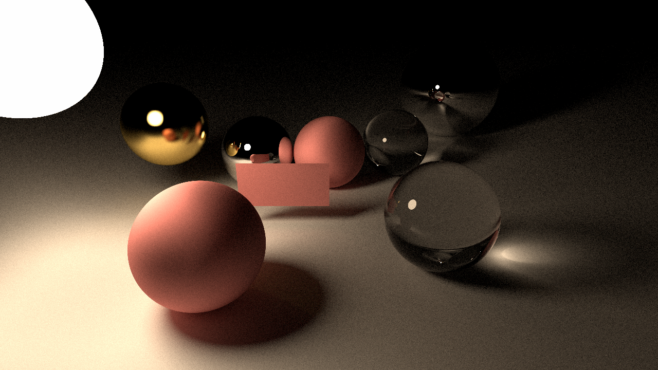
And this is what we get:

What a success! We have a rectangle in our scene but something is off. Look at the reflection of the rectangle on the mirror sphere. The backside of the rectangle looks like the same as the front side of the rectangle. That is not correct because no lights are reaching on there. It should be darker. This has happened because we have used one normal vector for both sides. So, we need a little more smart way to calculate the normal vector.
Normal vector and incident ray direction vector should point opposite ways.
Our general normal vector Vector3(0.0f, 0.0f, 1.0f) is okay if incident ray coming towards from the camera. But if it's coming towards the camera,
the normal vector should be flipped.
So, we need to determine these vectors are points the same direction or not. Since we have an axis-aligned rectangle, we can determine with a single dot product between incident ray direction and normal vector which points towards the camera. If the result of the dot product is negative, that means they are pointing in opposite directions. If the result is positive, they are pointing in the same direction. We don't want that.
Vector3 positiveZ = Vector3(0.0f, 0.0f, 1.0f);
float dot = DotProduct(ray->direction, positiveZ);
if (dot > 0) {
    // They are pointing in same direction
    // Normal vector should be flipped
    hitNormal = -positiveZ;
} else {
    hitNormal = positiveZ;
}
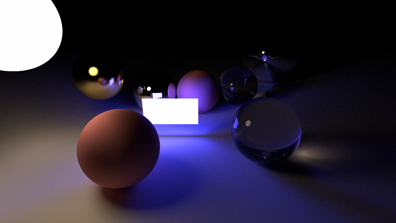
That looks more correct image. Now we can apply all types of material types to the rectangle. Here is a rectangle with emissive material applied:
Oriented Rectangles
So, that is cool but what if I want to rotate this light 90 degrees for making it like toplight. For that, I have to make an XZ plane aligned rectangle and write it's intersection code. What if I want to rotate 45 degrees? That is no option at all.
But what if we pretend like the rectangle already rotated and able to make intersection test, we rotate back to XY plane with incident ray and make hit test. That will work actually. Because we will not rotate the rectangle, we will rotate the incident ray. When I implemented this, I didn't know that this "Instead of rotating objects, rotate the rays" technique was used a lot in renderers.
When you using game engine editors, you create objects like spheres, etc. Then you start to move them around and rotate them maybe. That transform values are kept in matrices. And all the objects you created, still bounds to the world's origin point. You just specify how it's position far from the origin point of the world. This is what we are going to do. (We are not gonna do editor or something like that yet) We are going to create rectangles on the origin point and aligned with the XY plane. Then we are going to change it's transformation using matrices. On the intersection code, we are going to inverse the transformation operations.
For that, we need a 4D vector and 4x4 matrix classes. (Commit). Now, rectangle struct will be like this:
// XY plane axis-aligned rectangle
// RULE: Default Rectangle are 2 unit square and it's center point always on the origin.
// Use transform matrices to manupilate position, scale and orientation.
static const Vector3 rectDefaultMinPoint{ -1.0f, -1.0f, 0.0f };
static const Vector3 rectDefaultMaxPoint{  1.0f,  1.0f, 0.0f };
struct RectangleXY {
    Matrix4 scaleMatrix;
    Matrix4 translateMatrix;
    Matrix4 rotationMatrix;
};
We will adjust these matrices in the CreateScene function. In IntesectWorld function, we are multiplying these matrices with default points:
Matrix4 scaleTranslateMatrix = rect->translateMatrix * rect->scaleMatrix;
// These are the transformed rectangle points that we will use on hit testing.
Vector3 minPoint = (scaleTranslateMatrix * Vector4(rectDefaultMinPoint, 1.0f)).xyz();
Vector3 maxPoint = (scaleTranslateMatrix * Vector4(rectDefaultMaxPoint, 1.0f)).xyz();

// Hit testing
So far so good, we are rendering the same scene with matrices. But our goal is to rotate the rectangles, let's implement that. Like I said before, we will not rotate the rectangle, we will rotate the incident ray. So all I need is invert rectangle's rotation matrix and multiply with incident ray.
Matrix4 rayMatrix = Inverse(rect->rotationMatrix);
// Transform ray
// If a Vector3 represent a point; while we converting it to the Vector4, we set component w to 1.
// If a Vector3 represent a vector; while we converting it to the Vector4, we set component w to 0.
Vector3 rayOrigin = (rayMatrix * Vector4(ray->origin, 1.0f)).xyz();
Vector3 rayDirection = (rayMatrix * Vector4(ray->direction, 0.0f)).xyz();
And we get this:
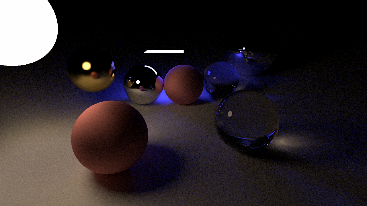
It rotated 90 degrees but around world origin. I want to rotate around its origin. So we need to translate back origin, rotate, and translate again:
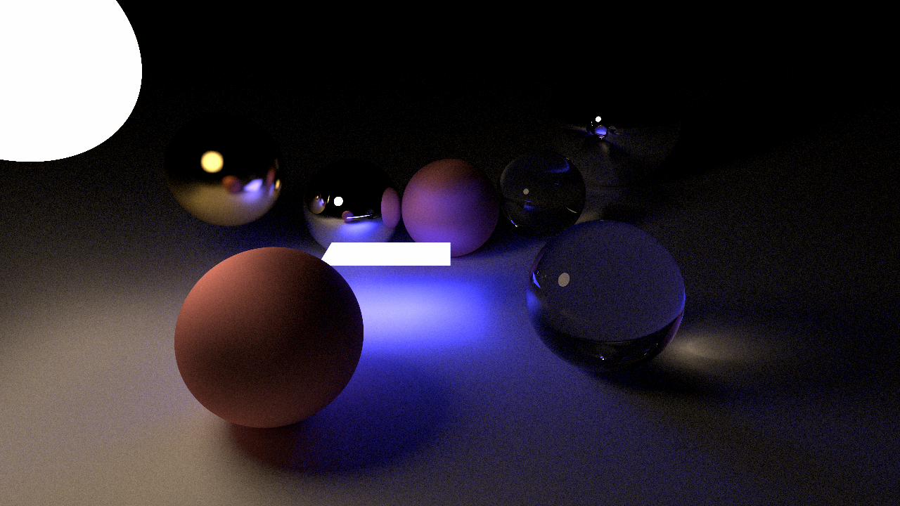
Matrix4 rayMatrix = rect->translateMatrix * Inverse(rect->rotationMatrix) * Inverse(rect->translateMatrix);
Now we get what we wanted:
Execution time is 3 times slower now and we have just one rectangle in the scene. We need to optimize this process. At least we have flexible rectangles. Now, I think it's time! Oh yeah, Cornell Box!
Cornell Box
We are going to need a lot of rectangles for the Cornell Box scene. So I've started to write some helper functions for creating rectangles. We need box types also. Boxes are essentially a shape which has 6 rectangles for faces. And the scene needs 2 boxes and 6 rectangles. 5 for the walls and 1 for the top light. After writing little bit boilerplate code we get this:
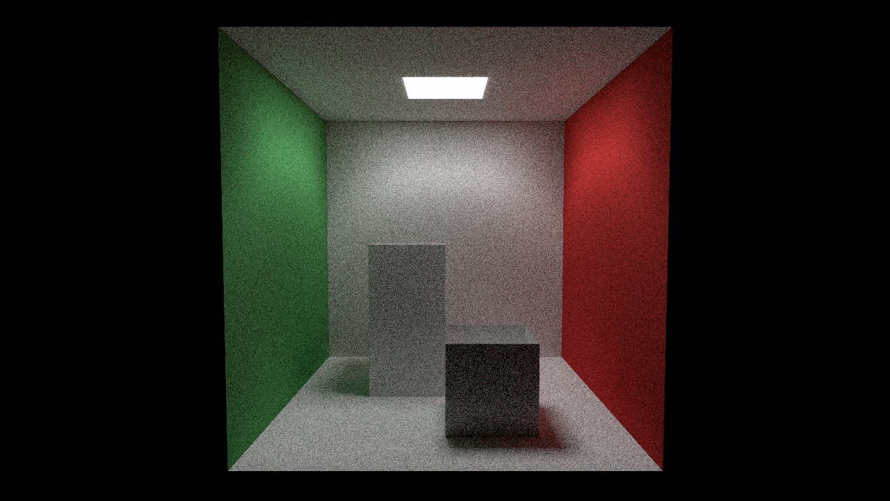
Yeah! It works! But this 512 spp image rendered in 10 minutes. Our raytracer is way slower now. Let's make some optimizations or should I say; fix stupid thigs.
So, the first one is obvious, right? Why we have a scale, translate and rotation matrices are stored separately. We can combine them into one transform matrix and use it's inverse for transforming rays.
struct RectangleXY {
    Matrix4 transformMatrix;
    // We keep rotation matrix seperate as well because we are using this for rotating the rectangle normal.
    // TODO: Instead of keeping rotation matrix, why not keep normal vector itself?
    Matrix4 rotationMatrix;
    uint32_t materialIndex;
};
With this improvement, our intersection code is now simpler. We don't transform rectangle coordinates at all. Now, we are only transforming incident rays.
for every rectangle:
    RectangleXY* rect = world->rectangles + rectangleIndex;

    Matrix4 rayMatrix = Inverse(rect->transformMatrix);
    Vector3 rayOrigin = (rayMatrix * Vector4(ray->origin, 1.0f)).xyz();
    Vector3 rayDirection = (rayMatrix * Vector4(ray->direction, 0.0f)).xyz();

    ... Hit testing ...
There are lots of things to optimize this code. For example, we only need an inverted version of the transform matrix. Why don't we invert the transformation matrix on the initialization stage and put that in rectangle struct? We will do further performance improvements in the next post.
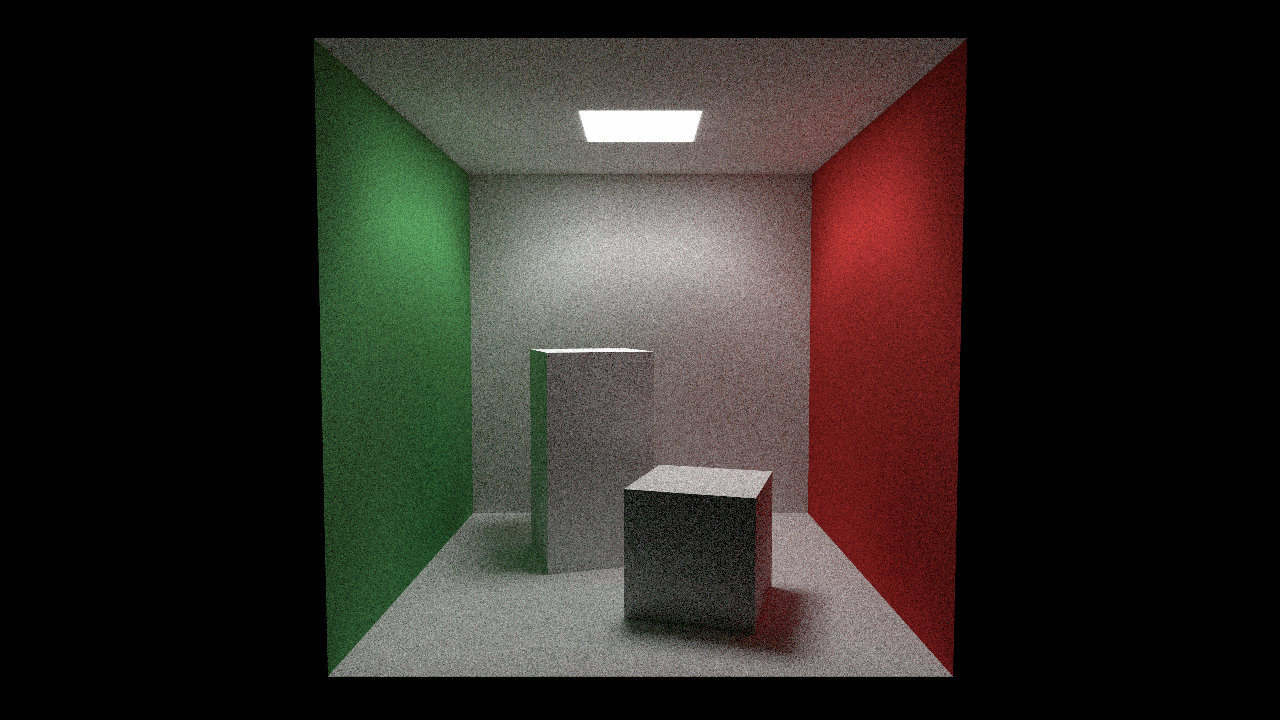
Also, in every Cornell Box scene, those two boxes are little rotated. So I've added a helper function to rotate boxes and we get this:
Learnings and what's next
The most valuable thing I learned when implementing these features is that instead of transform scene objects, we can transform the incident ray. This way is easier in some cases. Like rectangles in our case.
I've implemented this rectangle support first in GPU but I haven't finished yet. Next, we will be doing some optimizations, SIMD rectangles maybe? And we will finish our GPU implementation as well.
1534 Words
2019-07-23 17:30 +0300